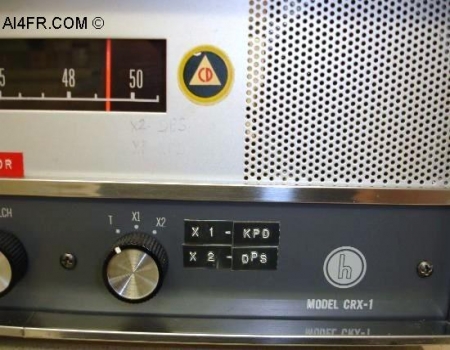
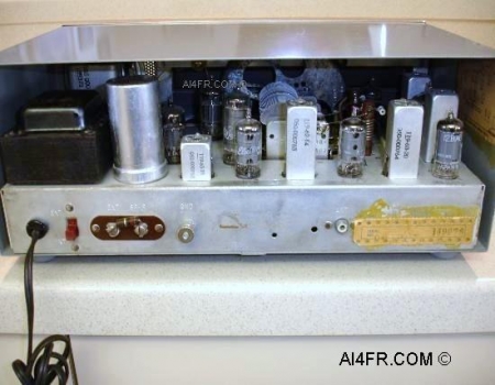
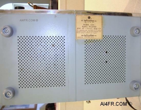
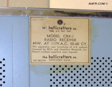
The photograph on the left shows the switch for the two optional crystals that were discussed in the text above. The optional crystals for this receiver are of the CR-23/U type. One crystal is required for each dial setting(X1 and X2) for a total of two crystals. To find the correct crystal frequency to purchase, a little bit of math is in order. Say you wanted a crystal frequency that would allow you to quickly monitor 33.180 megacycles on either of the two dial settings, X1 or X2. The formula for this is the crystal frequency in megacycles 33.180 - 4.500 / 2 which gives us 28.680 / 2 which equals 14.340 megacycles. So the crystal needed to quickly monitor 33.180 mHz would be 14.340. With this crystal installed in either the X1 or X2 slot the operator could quickly monitor the frequency of 33.180 without touching the tuning dial. All that would be required would be for the operator to simply turn the Crystal/Main tuning selector knob to the respective X1 or X2 position in which the crystal had been installed. Also in the picture on the left notice the round yellow edged sticker with a triangle in the center indicating this receivers past history from the cold war days. This sticker is the old United States Civil defense logo. The triangle emphasized the 3 step Civil Defense philosophy that was used before the foundation of FEMA and Comprehensive Emergency Management. Civil defense was an effort to prepare civilians for military attack. It uses the principles of emergency operations: prevention, mitigation, preparation, response, or emergency evacuation, and recovery. Programs of this sort were initially discussed at least as early as the 1920's but only became widespread after the threat of nuclear weapons was realized. Since the end of the Cold War, the focus of civil defense has largely shifted away from military attack to national and local emergencies and disasters. The new concept is described by a number of terms, each of which has its own specific shade of meaning, such as crisis management, emergency management, emergency preparedness, contingency planning, emergency services, and civil protection. The photograph on the right is of the back of the receiver. This picture displays the tube compliment and some of the other major components that are found on the top of the chassis. This radio has its own internal AC power supply circuitry as evident of the AC power cord, large black transformer and the can type electrolytic capacitor. I mention this power supply circuitry due to having another CRX-1 receiver in the collection that does not have this built in AC power supply. Starting at the left, the back panel plugs and switches are as follows, AC power cord, a red colored internal/external speaker switch, external speaker screw terminal connections, ground connection and on the right is the antenna connection which is located next to the paper sticker. The red switch located next to the power cord is used to select from either the front internal speaker or the speaker screw terminals located next to it. Besides connecting an external speaker to these screw terminals, Hallicrafters states that they can be used for headphones or a recording device. The manual goes on to say that any size of external speaker may be used and that a permanent magnet type speaker with 3 to 4 ohms is preferred. Across the external speaker screw terminals should be a 12 ohm 1 watt resistor when the internal speaker, headphones or a recording device is being used. This resistor should be removed when using an external speaker. |