|
|
| |
|
|
|
|
|
|
|
|
|
|
|
|
|
|
|
|
|
|
|
|
|
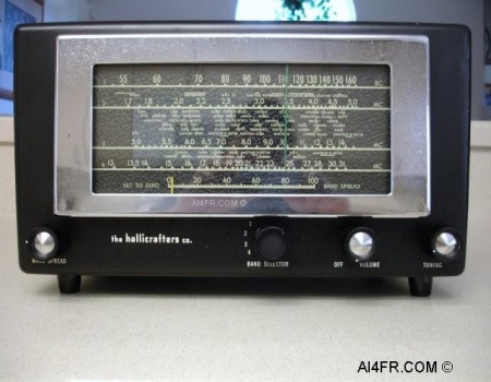
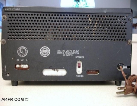
Production Year 1951 - 1953 at $39.95 The Hallicrafters 5R10A is a Superheterodyne, general coverage receiver that is used for the reception of AM and CW signals. The 5R10A receiver incorporates 5 tubes in its circuit and has 4 bands with continuous coverage from 540 KHz to 31 MHz. The first band covers 540 KC to 1650 KC, the second band covers from 1.65 MHz to 5.1 MHz, the third band covers from 5 MHz to 14.5 MHz, and the fourth band covers from 13 MHz all the way up to 31 MHz. The Intermediate Frequency(IF) of this receiver is the standard 455 KHz. The internal roof mounted speaker is of the permanent magnet moving coil design that measures five inches across and has a voice coil impedance of 3.2 ohms. Received signals exit through a perforated section on the top of the unit. If headphones are to be used, the receiver requires a set with a high impedance in the range of 1500 to 5000 ohms. This radio uses the standard #47 bulb for the dial lamp. Scanning across the front panel from left to right, the operator controls and their functions are as follows: the Bandspread knob, in the center of the receiver is the four position Band Selector knob that is used to select one of the four bands for reception. Next we run into the On/Off and Volume control knob, and at the bottom right hand corner we have the Main Tuning knob. The power source requirements are 105 to 125 volts DC or between the same voltage range but with 60 cycles AC. The normal power consumption of the receiver is 30 watts. It is also possible to operate the receiver from a 210 to 250 volt AC or DC power source by using a special line cord adapter with the Hallicrafters accessory part number of 87D1566. The receiver employs a total of five vacuum tubes. Their function is as follows, a 12SA7 = Oscillator and Mixer, 12SK7 = I.F., 12SQ7 = Detector and 1st Audio Amplifier, 50L6 = Audio Output, and a 35Z5 that is used as a rectifier. The Hallicrafters 5R10A also features band spread tuning. The band spread dial is located under the larger main tuning dial and is calibrated from 0 to 100. To operate the band spread dial, set the main tuning dial to the high frequency limit of the range of frequencies to be covered and then tune stations in with the band spread control. For example: say that the 40 meter amateur band is to be covered. Set the main tuning dial pointer to 7.3 MHz and tune in the stations with the band spread control. The band spread control allows for fine tuning of stations and forces the operator to move across the frequency spectrum at a much slower pace, thus helping to insure that weak stations are not missed. Tuning the bandspread control from 0 to 100 tunes the receiver progressively lower in frequency. One thing to keep in mind is that the calibration of the main tuning dial will only be correct when the band spread dial is set to zero. The photograph on the right is of the back of the radio. The connections and such found here are as follows, from left to right, 3 terminal antenna connections, run number, a switch to choose between the internal speaker and headphones, headphone connectors, and at the right is the power cord. The 3 terminal antenna strip is marked "A1", "A2" and "G" and known as Antenna 1, Antenna 2 and Ground. A jumper bar consisting of a strand of wire is normally connected between terminals "A2" and "G" for single wire antenna systems as well as unbalanced antenna transmissions lines. For a doublet antenna system with a balanced transmission line, the jumper between "A2" and "G" would be disconnected and the transmission line from the antenna would be connected to terminals A1 and A2. If a concentric transmission line(coaxial cable) with a grounded outer conductor is used, connect the inner conductor to terminal "A1" and the outer conductor to "A2" followed by a jumper wire between terminals "A2" and "G". The station ground connection is to be connected to the "G" terminal. The receiver featured on this page is nearly identical to the Hallicrafters 5R100A. The main difference being the color of the case. The 5R100A is a hammertone gray color while the receiver featured here is a smoky black color. Both radios and including the non "A" models are also very similar electrically to the Hallicrafters model S-38D. |
|
|
|
|
|
|
|
|
|
|
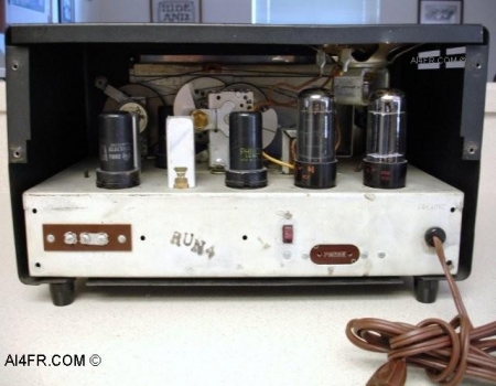
The photograph on the left is of the rear of the radio with the back cover removed. This picture displays the tube compliment and some of the other major components that are found on the top of the chassis. In the picture on the right, notice the small white dots on some of the components. It is most noticeable on the large orange banded resistor in the lower right corner of the photograph. The white dot on the resistor is plain old White-Out which is easily removed if desired. The reason it is present on the components is due to the fact that after I check a component and I know that it is within spec's I mark it. Granted, this radio is not complicated and is very basic, but it is an old habit that I got into doing some years ago. Another reason I mark the various components in such a fashion is that at a later date should the radio need service, a quick glance will tell me whether a certain component was within specifications the last time the radio was serviced. |
|
|
|
|
|
|
|
|
|
|
|
|
|
|
|
|
|
|
|
|
|
|
|
|
|
|
|
|
|
|
|
|
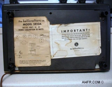
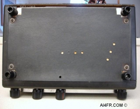
These next two photographs are of the bottom of the radio with the bottom cover in place. The left photograph shows a couple of paper stickers that were applied by Hallicrafters. These stickers show the tube complement as well as the tube types and their location to the major components on the top of the chassis, such as the variable air capacitor and transformers. The sticker on the left reads as follows, "the hallicrafters co. MODEL 5R10A 105-125 VOLTS AC - DC". Then underneath the chassis component layout it reads, "This Apparatus Uses Inventions Of U.S. Patents Licensed By Radio Corporation Of America And Hazeltine Research Inc. Licensed Patent Numbers Will Be Supplied Upon Request. CHICAGO U.S.A.". The sticker on the right reads as follows, "IMPORTANT! For your protection, this receiver has been properly adjusted and sealed at the factory. Breaking these seals without written permission from the factory or dealer will void your RMA guarantee.". The photograph on the right shows the bottom cover attached to the receiver but purposely installed upside down. What I have done here is turn the bottom cover around and put the paper labels on the inside of the receiver. I did this in the hopes of saving the stickers some wear and tear damage from the normal day to day operating of the radio. The holes in the bottom cover allow for minor adjustments of the oscillator and converter stage trimmers: however for a complete alignment, the chassis will need to be removed from the cabinet. To preform a proper alignment a standard RMA(Radio Manufacturers Association) dummy load antenna is required. The RMA dummy antenna consists of a 0.0002 MFd capacitor that is in series with a 20 uH RF choke. The choke or inductor is shunted by a .0004 MFd capacitor in series with a 400 ohm non-inductive resistor. The RMA antenna sounds more complicated then it really is. Please click on RMA Schematic for details on this antenna and why it should be used. If the cabinet is ever removed from the chassis, the rubber grommets, fiber washers and/or nylon insulators around the feet should be inspected and replaced if they are damaged. It is very important that the cabinet be insulated from the chassis. WARNING!! It is very important that you do not rely on these insulators a half a century later. A lot could go wrong such as, are they still in good condition, did a previous owner reassemble the radio properly, and so on. With these AC/DC sets, depending on which way the power cord is plugged into the wall can put the entire receiver at 120 volts above ground. This means that if the operator has one body part resting on an earth ground and reaches over and touches an exposed part of the receiver, the operator can receive a potentially fatal shock. |
|
|
|
|
|
|
|
|
|
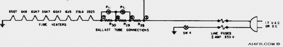
The partial schematic above is for the Hallicrafters S-22R receiver. This schematic would feel right at home with many of the AC/DC receivers, or numerous other electronic items that are built this way. There is no power supply transformer in the circuit of these items which makes them dangerous if the operator becomes careless. Actually, the reason the set can run from a DC power source is because there is no transformer. Today, an item built this way and with a metal cabinet would never get past the Underwriters Laboratory(UL). In fact, if you were to take a survey of the electrical items in your house, what you will most likely find is that just about every appliance with a metal case has a three prong power cord attached to it. As seen in the schematic above, the item will work no matter which way it is plugged into the wall. One way allows the chassis to be connected to the hot wire in the home wiring, while flipping the plug the other way connects the chassis to the neutral side of the house wiring. Either way can be dangerous as both the hot and the neutral house wires in the U.S. carry current. Even though at the fuse panel both the neutral and ground wires go to the same place. Picture this, the receiver cabinet is hot with 120 volts of AC. You have a hand resting on a desk lamp that uses an older non-polarized power cord or is grounded by a newer 3 prong plug, or your hand is resting on the station ground, or your feet are propped up on the heater, or a thousand other possible ways you could easily be at ground potential, now you reach for a switch on this radio and ZAP, the current runs through your body as it makes its way to ground and kills you. Now your wife becomes a widow and we see your stuff listed at auction under the title "From the estate of a SK". I realize that this sounds harsh, but in most cases there are no second chances. What's that I hear you say? You fully understand the dangers and will watch out for this? What about a family member when you are not home? Do they also understand the danger? Do not risk it. Explain the dangers to them and check the voltage on the chassis with your VOM with the on/off switch in both positions. An isolation transformer can also be used, or better yet, unplug the device when you are away. |
|
|
|
|
|
|
|
|
|
|
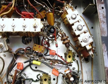
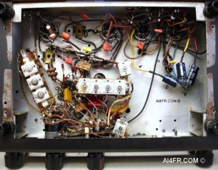
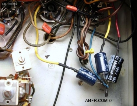
These last two pictures were taken after the restoration process was complete. The photograph on the left is of the bottom of the 5R10A with the bottom cover removed. In this picture we can see the entire "add the solder by the inch" circuitry. This radio design is just a slight step up on the evolutionary scale from the all American five receivers. In other words, they are not that complicated and there is a lot of room to move around. The little orange things are capacitors and are commonly referred to as "orange drop capacitors". It is often recommended to replace all of the molded paper and waxed paper capacitors in these older receivers, which has been done for this restoration. The reason being is that over time the old capacitors may start to dry out and become open, shorted or leak which can hurt the performance of the receiver and possibly cause serious damage to some of the components. The photograph on the right is a close up of the new electrolytic capacitors(3 blue things) that have been installed. Some times when I do these restorations I will drill out the gunk from inside the old original capacitor and stuff the new replacements inside. I normally do this so that the radio would keep its original appearance. Capacitors that are made today are not only sturdier and more precise, but are also much smaller. A capacitor from yesteryear that was the size of a roll of quarters is now the size of a pencil eraser today. In most cases, the new replacement capacitors will easily fit inside the body of the old capacitor. Some folks have been known to take this a step further and go so far as as to even stuff both the waxed paper and molded paper capacitors to give the set a museum quality restoration. As an added touch I have installed heat shrink tubing over all of the bare wire on the positive side of the electrolytic capacitors. The heat shrink tubing can be thought of as carpenters caulk, it gives the work a nice and neat appearance. Did you notice that all of the electrolytic capacitors have the same ground connection? Before I solder any wires or leads to the chassis or to the tube pins, I clean the oxidation and other gunk from the connection point with a Dremel tool using a wire brush attachment. Resources: Radios by Hallicrafters with Price Guide by Chuck Dachis Hallicrafters owners manual Sam's photofacts by Howard W. Sams & Co., Inc. |
|
|
|
|