|
|
| |
|
|
|
|
|
|
|
|
|
|
|
|
|
|
|
|
|
|
|
|
|
|
|
|
|
|
|
|
|
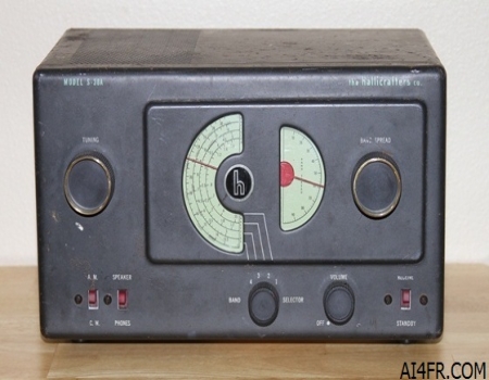
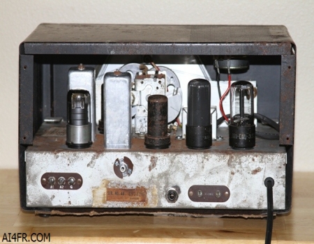
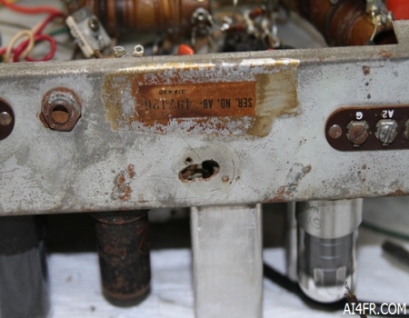
Production Year 1946 - 1947 at $49.50 This Hallicrafters S-38A is the second version of the S-38 family that was originally released in 1946. The Hallicrafters S-38 line included the models S-38, S-38A, S-38B, S-38C, S-38D, S-38E, S38EB and S-38EM. There are two versions of the S-38 without a letter suffix that is known to exist. The original S-38 had 6 tubes, a metal bottom cover and a smooth black finish on the cabinet. The second version of the S-38 which started production just prior to the model S-38A, had only five tubes, a cardboard bottom cover and a black wrinkle finish on the cabinet. All of the later models were essentially the same as the S-38A with the difference being the color and finish on the case and dials, some back panel changes and the way the power cord was attached. Although the C model used a 12SG7 tube rather then a 12SK7 tube as the IF amplifier. The A model had a smooth black finish, the B model had a black wrinkle finish, the C model had a Hammartone gray finish, the D model had a smooth gray finish, the E model was a smooth gray, the EB model had a beige finish while the EM model was a mahogany color. Beginning with the S-38D Hallicrafters radically changed the look of the receiver. It no longer had the half moon shaped dials, but rather a large rectangle frequency display very much like the Hallicrafters 5R10A. Starting with the E models, Hallicrafters added a BFO injection control on the rear apron of the chassis and changed the tube line up a bit. The Hallicrafters S-38 series of receivers remained in production from 1946 until 1961, an unheard of time span by the standards of today. The Hallicrafters S-38A is a Superheterodyne, general coverage receiver that is used for the reception of AM and CW signals. The S-38A receiver incorporates 5 tubes in its circuit and has 4 bands with continuous coverage from 550 KHz to 31 MHz. The first band covers 550 KC to 1650 KC, the second band covers from 1.7 MHz to 5.1 MHz, the third band covers from 5 MHz to 14.5 MHz, and the fourth band covers from 13 MHz all the way up to 31 MHz. The Intermediate Frequency(IF) of this receiver is the standard 455 KHz. The internal roof mounted speaker is of the permanent magnet moving coil design that measures five inches across and has a voice coil impedance of 3.2 ohms. Received signals exit through a perforated section on the top of the unit. If headphones are to be used, the receiver requires a set with 500 to 2000 ohm impedance. This radio uses the standard #47 bulb for the dial lamp. The Hallicrafters S-38A also features band spread tuning. The band spread dial is located to the right of the larger main tuning dial and is calibrated from 0 to 100. To operate the band spread dial, set the main tuning dial to the high frequency limit of the range of frequencies to be covered and then tune stations in with the band spread control. For example: say that the 40 meter amateur band is to be covered. Set the main tuning dial pointer to 7.3 MHz and tune in the stations with the band spread control. The band spread control allows for fine tuning of stations and forces the operator to move across the frequency spectrum at a much slower pace, thus helping to insure that weak stations are not missed. Tuning the bandspread control from 0 to 100 tunes the receiver progressively lower in frequency. One thing to keep in mind is that the calibration of the main tuning dial will only be correct when the band spread dial is set to zero. The photograph above on the left is of the front of the radio. Scanning across the front panel from left to right, the operator controls and their functions are as follows: at the top left is the Main Tuning knob, at the bottom left we run into the first of three front panel switches. This first switch is used to select the desired receiving mode and is labeled A.M. on the top and C.W. on the bottom. The next switch that we come to allows the operator to select between the internal Speaker or the use of Headphones. In the center of the receiver is the four position Band Selector knob that is used to select one of the four bands for reception. Next we run into the On/Off and Volume control knob. From here we move upwards and find the Bandspread knob. At the bottom right hand corner we have the last of the three switches which is labeled Receive on the top and Send on the bottom. The Send/Receive switch removes the plate voltage from the tubes of the S-38B which makes the receiver inoperative during times of transmission. This switch can also be used to conserve power during a stand-by period when it would be important to have the radio spring to life with just a flick of a switch instead of having to wait for the tubes to warm up. The 5 tubes that are used in this receiver along with their functions are as follows: 12SA7 = Mixer/Oscillator, 12SK7 = IF Amplifier & BFO, 12SQ7 = Detector and 1st Audio Amplifier, 50L6GT = Audio power amplifier, and a 35Z5 employed as a Rectifier. The power source requirements are 105 to 125 volts DC or between the same voltage range but with 60 cycles AC. The normal power consumption of the receiver is 30 watts. It is also possible to operate the receiver from a 210 to 250 volt AC or DC power source by using a special line cord adapter with the Hallicrafters accessory part number of 87D1566. The photograph above on the right is of the back of the radio. The connections and such found here are as follows, from left to right, 3 terminal antenna connections, serial number, above the serial number is a previous owner modification consisting of an RCA jack and to the right of it is another modification of a phono jack, next we find the headphone connectors, and at the right is a new power cord. The model S38B incorporates a power cord design that removes power from the receiver when the back panel is removed. It does not appear that the S38A used this safety design. The 3 terminal antenna strip on the back panel is marked "A1", "A2" and "G" and known as Antenna 1, Antenna 2 and Ground. A jumper bar consisting of a strand of wire is normally connected between terminals "A2" and "G" for single wire antenna systems as well as unbalanced antenna transmissions lines. For a doublet antenna system with a balanced transmission line, the jumper between "A2" and "G" would be disconnected and the transmission line from the antenna would be connected to terminals A1 and A2. If a concentric transmission line(coaxial cable) with a grounded outer conductor is used, connect the inner conductor to terminal "A1" and the outer conductor to "A2" followed by a jumper wire between terminals "A2" and "G". The station ground connection is to be connected to the "G" terminal. |
|
|
|
|
|
|
|
|
|
|
|
|
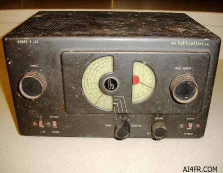
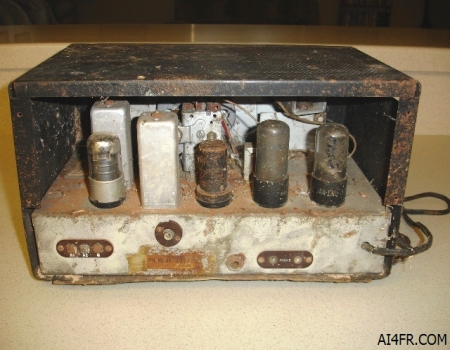
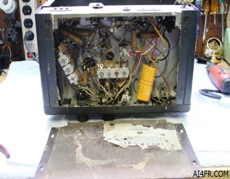
These next two photographs show the front and back of the S38A in the condition in which I found it. This receiver was found in a small wooden shed that leaked when it rained and had no doors or windows left in place. The exposure to the elements did a lot of damage to this receiver. The aftermarket phono plug on the back was nearly rusted shut. |
|
|
|
|
|
|
|
|
|
|
|
|
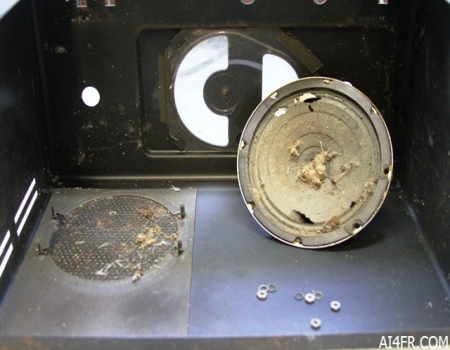
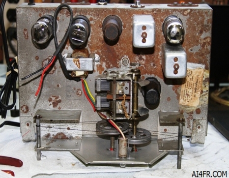
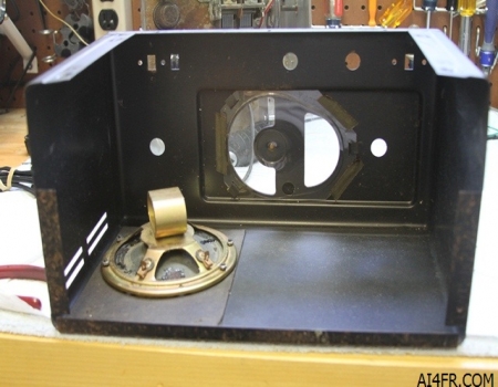
Here we have two more photographs of the S38A showing the condition of the radio before any restoration was preformed. After removing the bottom cover I was delighted to learn that much of the guts escaped major damage. The picture on the right is of the cabinet with the chassis removed. The speaker was destroyed beyond all repair as the voice coil was rusted in place. The termite wings are a result of this radio being stored in a wooden shed that was infested by these insects. |
|
|
|
|
|
|
|
|
|
|
|
|
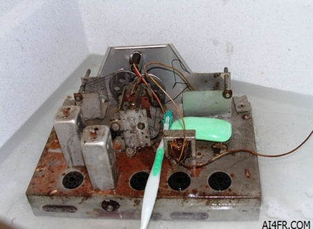
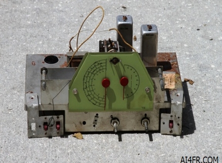
The photograph on the left shows one way to clean up such a dirty receiver. It is bath time. This S38A was so dirty that I did not bother to remove the broken dial cord or spring before scrubbing it. After the tubes were removed I cut off what was left of the power cord and removed the chassis from the cabinet. From there it went straight to the bath. The picture on the right is nothing more than the radio out sunning after its bath. The greasy fingerprints seen at the bottom right of the green display would not come off. They are still there to this day. With the chassis installed in the cabinet these fingerprints cannot be seen. |
|
|
|
|
|
|
|
|
|
|
|
|
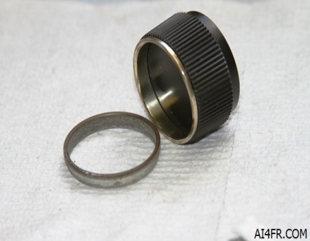
The photograph on the left displays the holes drilled into the back of the chassis by a previous owner. Someone installed an RCA jack at this location. The wires on the RCA jack was not connected underneath the chassis. I installed a new RCA jack to cover the hole but did not connect it to the circuit. The picture on the right shows the metal rings that are found on the inside of the tuning knob and the band spread knob. The ring that is attached to the knob has been cleaned while the other one has not. To clean this ring I used a Dremel tool with a wire wheel attachment to remove the crust. Next I used a little Brasso with a cloth polishing wheel on the Dremel tool. This procedure returned the rings to their original brilliance. To clean the plastic knob I used an old toothbrush and a little soap and water. Each ring on both of the knobs snapped apart/off easily. To do this I used a flat head screwdriver placed between the inside bottom of the ring and the knob. With a gentle twist the ring popped right off. The Dremel is a permanent tool on the workbench much the same as a screwdriver or wire strippers. To see some of the other uses for a Dremel tool please click HERE. |
|
|
|
|
|
|
|
|
|
|
|
|
|
|
|
|
|
|
|
|
|
|
|
|
|
|
|
|
|
|
|
|
|
|
|
|
|
|
|
|
|
After replacing most of the capacitors, one dial cord, several resistors, #47 blub, power cord, speaker, and one tube, the S38A was still dead in the water. Well at least almost dead in the water.The tubes would get warm and the panel lamp would light but that was the only indication of life in this receiver. So I checked the voltages on the tube pins for the audio output tube and found several that were way off. The voltages were very low. I also used a Conar model 230 signal tracer and learned that I had an audio signal going into the final output audio tube but nothing coming out. Hmmm, the tube tested good in my tube tester. Of course the best tube tester in the world is the actual circuit that the tube will be installed in. After a few more tests such as swapping out the tube I was convinced that the tube was good. Studying the circuit and the schematic showed that the pins which had the low voltages are connected to the audio transformer. I unsoldered the audio transformer and checked it with an ohm meter. The primary side of this transformer was wide open, it was bad. Off to the junk drawer I went. I found another transformer that was close. By close I mean it had had a center tapped secondary like the original and the mounting holes were the same. But what about the rest of the specifications? I did not know. So I ran a few tests on it as can be seen in the picture on the left. With the new audio transformer installed the radio came to life. Checking the voltages on the audio output tube showed no problems. I got lucky. This junk box transformer would work!! The old transformer was pop riveted to the chassis. Removing it simply meant drilling out the pop rivets. To do this I simply used the Dremel tool again. The photograph on the right shows the junk box transformer installed. For a slightly neater appearance I placed black heat shrink tubing around the speaker wires. |
|
|
|
|
|
|
|
|
|
|
|
|
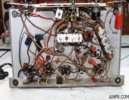
The photograph on the left is of the bottom of the chassis after the restoration is complete. In this picture we can see the entire "add the solder by the inch" circuitry. This radio design is just a slight step up on the evolutionary scale from the all American five receivers. In other words, they are not that complicated and there is a lot of room to move around. The little orange things are capacitors and are commonly referred to as "orange drop capacitors". It is often recommended to replace all of the molded paper and waxed paper capacitors in these older receivers which has been done for this restoration. The reason being is that over time the old capacitors may start to dry out and become open, shorted or leak which can hurt the performance of the receiver and possibly cause serious damage to some of the components. Also notice on the left hand side that new electrolytic capacitors(3 blue things) have been installed as well. Some times when I do these restorations I will drill out the gunk from inside the old original capacitor and stuff the new replacements inside. I normally do this so that the radio would keep its original appearance. Capacitors that are made today are not only sturdier and more precise, but are also much smaller. A capacitor from yesteryear that was the size of a roll of quarters is now the size of a pencil eraser today. In most cases, the new replacement capacitors will easily fit inside the body of the old capacitor. Some folks have been known to take this a step further and go so far as as to even stuff both the waxed paper and molded paper capacitors to give the set a museum quality restoration. Before I solder any wires or leads to the chassis or to the tube pins, I clean the oxidation and other gunk from the connection point with a Dremel tool using a wire brush attachment to clean the connection point. After all the bad components were replaced it was time to do an alignment. Surprisingly the alignment was very close. The I.F. just needed to be tweaked a little. All that needs to be done now is to install the chassis back into the cabinet. For a much better restoration job I could have done a little re-wiring and installed a fuse between the AC power cord and the on/off switch. For a proper restoration one should install both an X and Y type capacitors across the power line(X type) and going to ground(Y type). Should one of these safety capacitors(X or Y) fail they are designed to open. Should an orange drop capacitor fail it could create a short circuit. The orange drop capacitor seen in the lower left hand corner should be replaced with a Y type capacitor. The picture on the right is of the cabinet with the new speaker installed. This was another junk box item that was in need of repair. The speaker cone had numerous holes in it and was in very bad shape. I was not sure if it could be fixed but it was worth a try. I did the same trick I used on the speaker in the GE model 876 which was using glue and a paper towel patch for the holes. After installing the chassis back into the cabinet I decided to give the radio a play test before installing the knobs, feet and bottom. Turning the set on it sounded horrible. It sounded like the station was just not tuned in properly and no amount of turning either the tuner knob or the bandspread knob cured the problem. I did not notice the distortion when the speaker was sitting on the bench while testing the new audio transformer. As it turns out, the speaker was just to far gone and my cone repair did not work this time. The magnet was clean with no slivers of metal rattling around. Off to the junk box I went and found a modern speaker that fit the mounting bolts on the cabinet and sounded perfect. In fact, this little S38A is one of the best sounding receivers in the house. |
|
|
|
|
|
|
|
|
|
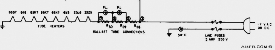
If the cabinet is ever removed from the chassis, the rubber grommets, fiber washers and/or nylon insulators should be inspected and replaced if they are damaged. It is very important that the cabinet be insulated from the chassis. WARNING!! It is very important that you do not rely on these insulators a half a century later. A lot could go wrong such as, are they still in good condition, did a previous owner reassemble the radio properly, and so on. With these AC/DC sets, depending on which way the power cord is plugged into the wall can put the entire receiver at 120 volts above ground. This means that if the operator has one body part resting on an earth ground and reaches over and touches an exposed part of the receiver, the operator can receive a potentially fatal shock. The partial schematic above is for the Hallicrafters S-22R receiver. This schematic would feel right at home with many of the AC/DC receivers, or numerous other electronic items that are built this way. There is no power supply transformer in the circuit of these items which makes them dangerous if the operator becomes careless. Actually, the reason the set can run from a DC power source is because there is no transformer. Today, an item built this way and with a metal cabinet would never get past the Underwriters Laboratory(UL). In fact, if you were to take a survey of the electrical items in your house, what you will most likely find is that just about every appliance with a metal case has a three prong power cord attached to it. As seen in the schematic above, the item will work no matter which way it is plugged into the wall. One way allows the chassis to be connected to the hot wire in the home wiring, while flipping the plug the other way connects the chassis to the neutral side of the house wiring. Either way can be dangerous as both the hot and the neutral house wires in the U.S. carry current. Even though at the fuse panel both the neutral and ground wires go to the same place. Picture this, the receiver cabinet is hot with 120 volts of AC. You have a hand resting on a desk lamp that uses an older non-polarized power cord or is grounded by a newer 3 prong plug, or your hand is resting on the station ground, or your feet are propped up on the heater, or a thousand other possible ways you could easily be at ground potential, now you reach for a switch on this radio and ZAP, the current runs through your body as it makes its way to ground and kills you. Now your wife becomes a widow and we see your stuff listed at auction under the title "From the estate of a SK". I realize that this sounds harsh, but in most cases there are no second chances. What's that I hear you say? You fully understand the dangers and will watch out for this? What about a family member when you are not home? Do they also understand the danger? Do not risk it. Explain the dangers to them and check the voltage on the chassis with your VOM with the on/off switch in both positions. An isolation transformer can also be used, or better yet, unplug the device when you are away. Resources: Radios by Hallicrafters with Price Guide by Chuck Dachis Hallicrafters owners manual Sam's photofacts by Howard W. Sams & Co., Inc. Television and Radio repairing by John Markus |
|
|
|
|